6.4. Configuring Discharge Calculation#
If no channel profile is stored on the device, or if the existing profile has been deleted, the Profile page will be empty and a new channel profile must be defined.
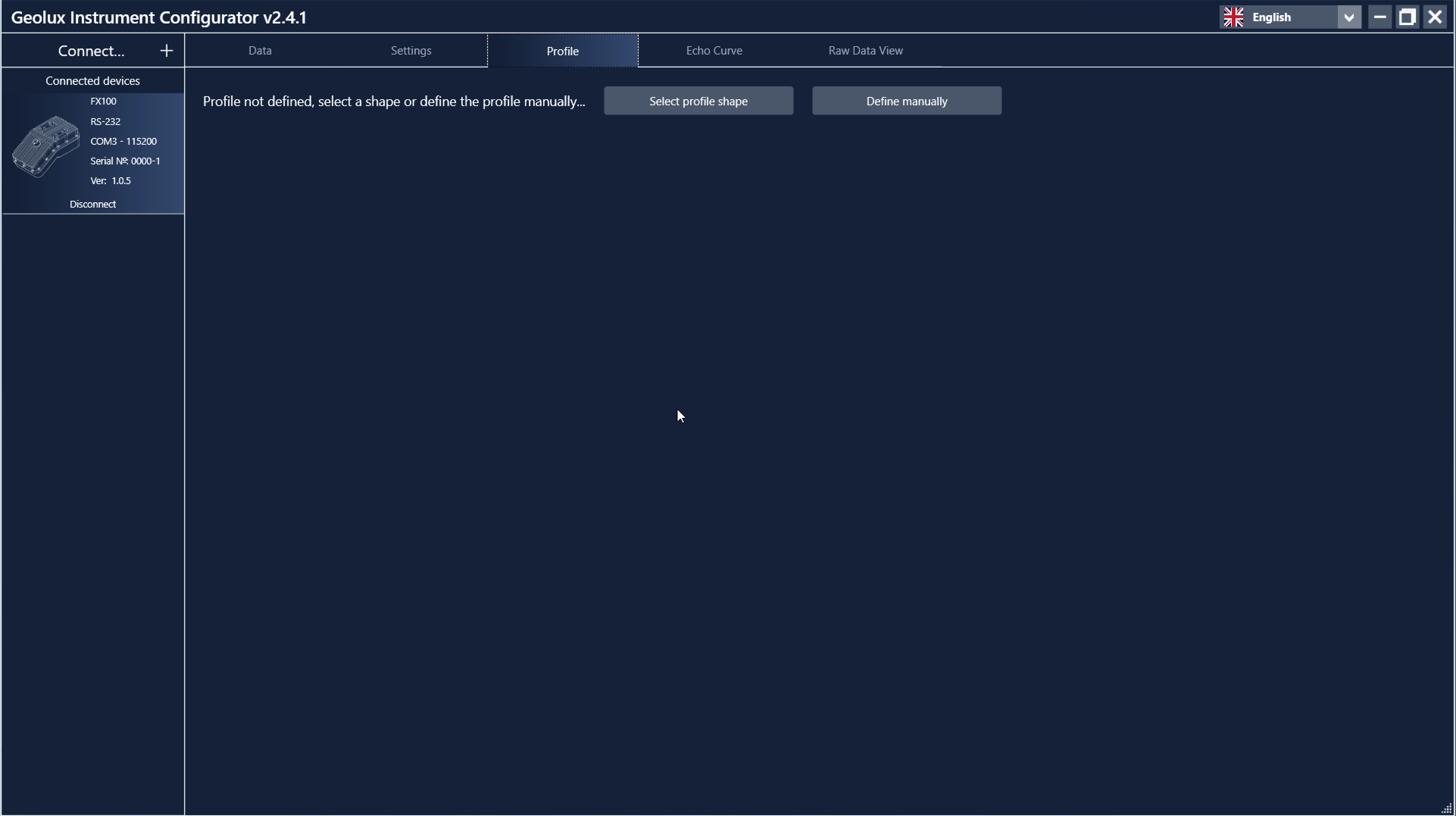
Empty channel profile page.#
There are two ways to define the channel profile:
Manual definition – Enter the X and Y coordinates of each profile point. This method is typically used for natural channels where bathymetric survey data is available.
Predefined shapes – Select one of the predefined channel shapes, such as rectangular, trapezoidal, or circular. This method is intended for concrete channels, culverts, and sewer systems.
If a LiDAR scan has been saved on the LiDAR page, as described in 6.3. Using LiDAR, the scanned cross-section is displayed on the Profile page as the channel profile and is used for the discharge calculation. The scanned profile can always be overridden manually: its points can be edited in the same way as manually entered points, or the profile can be deleted and defined again using either of the two methods described above.
Manual Channel Profile Configuration#
Click Define manually to open an empty channel profile.
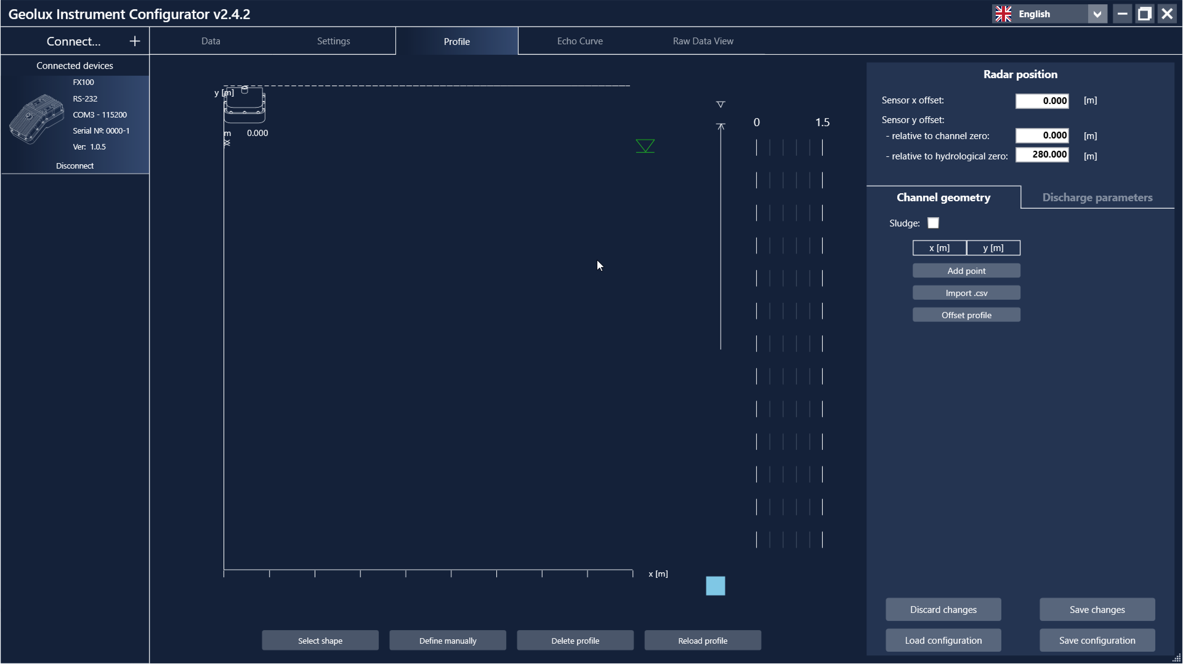
Manual channel profile definition.#
Begin by entering the channel profile points. Add points individually by clicking Add point, then enter the X and Y coordinates.
The X coordinate starts at 0 at the left edge of the channel and increases towards the right.
The Y coordinate may use any vertical datum. For example, it can represent:
elevation above mean sea level,
depth referenced to the channel bottom,
any other local vertical datum.
After entering the coordinates, click Set to save the point. Additional points cannot be added until the current point has been confirmed. To remove a point, click Delete.
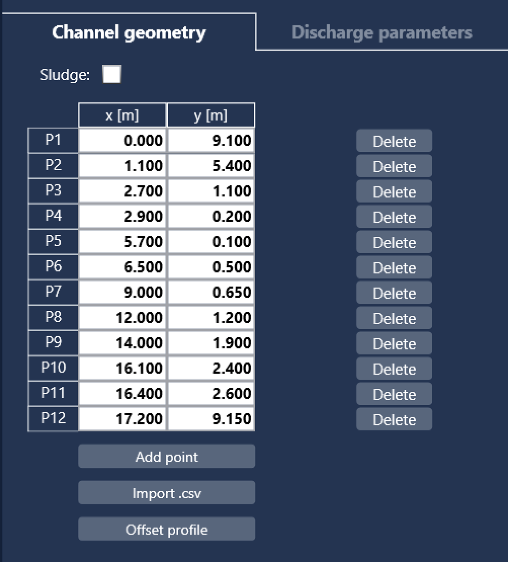
Channel profile coordinate editor.#
Importing Profile from a CSV File#
If channel bathymetry is available in a CSV file, the profile can be imported instead of entering points manually.
Click Import .csv, select the file, and review the imported coordinates. Before importing, select the measurement unit used in the CSV file.
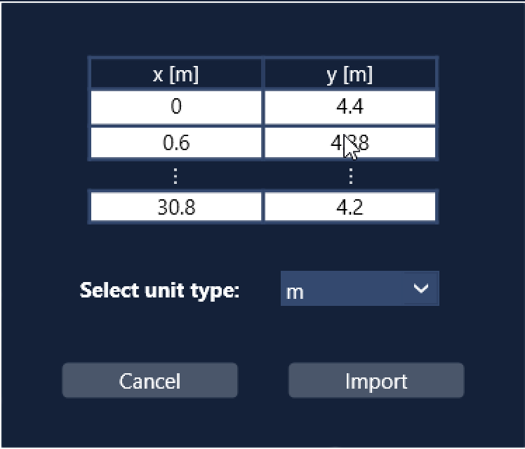
CSV profile import preview.#
After clicking Import, an optional vertical offset can be applied to all Y coordinates. This is useful when the CSV data uses a different vertical datum than the one intended for the FX200 configuration.
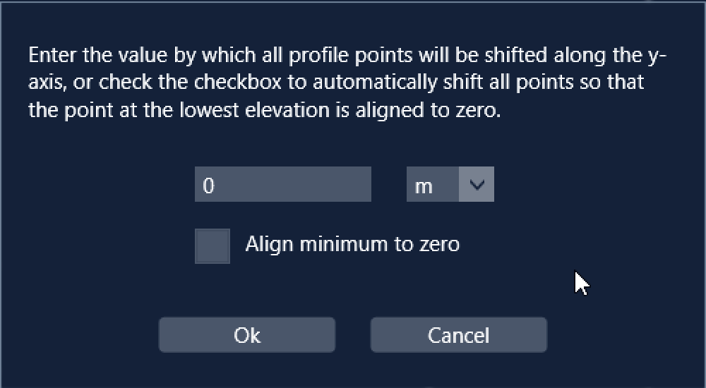
Applying a vertical offset to imported profile coordinates.#
Configuring Radar Position#
After defining the channel profile, configure the radar position in the Radar position pane.
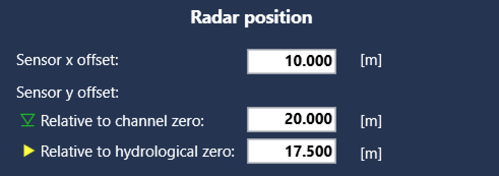
Radar position settings.#
Sensor X offset
Horizontal distance from the leftmost channel point.
Sensor Y offset (relative to channel zero)
Vertical sensor position using the same datum as the channel profile. For example, if the profile uses elevations above mean sea level, this value must use the same reference. If the profile uses the channel bottom as zero, this value is the distance from the radar to the channel bottom.
This parameter is used to calculate the wetted cross-sectional area from the measured distance to the water surface.
Sensor Y offset (relative to hydrological zero)
Equivalent to the Vertical position setting on the Settings page. It is used only to convert the measured distance to the reported water level and does not affect discharge calculation.
This value may be the same as the channel reference, but different vertical datums can also be used.
After the radar position has been configured, the channel profile is displayed together with the sensor location.
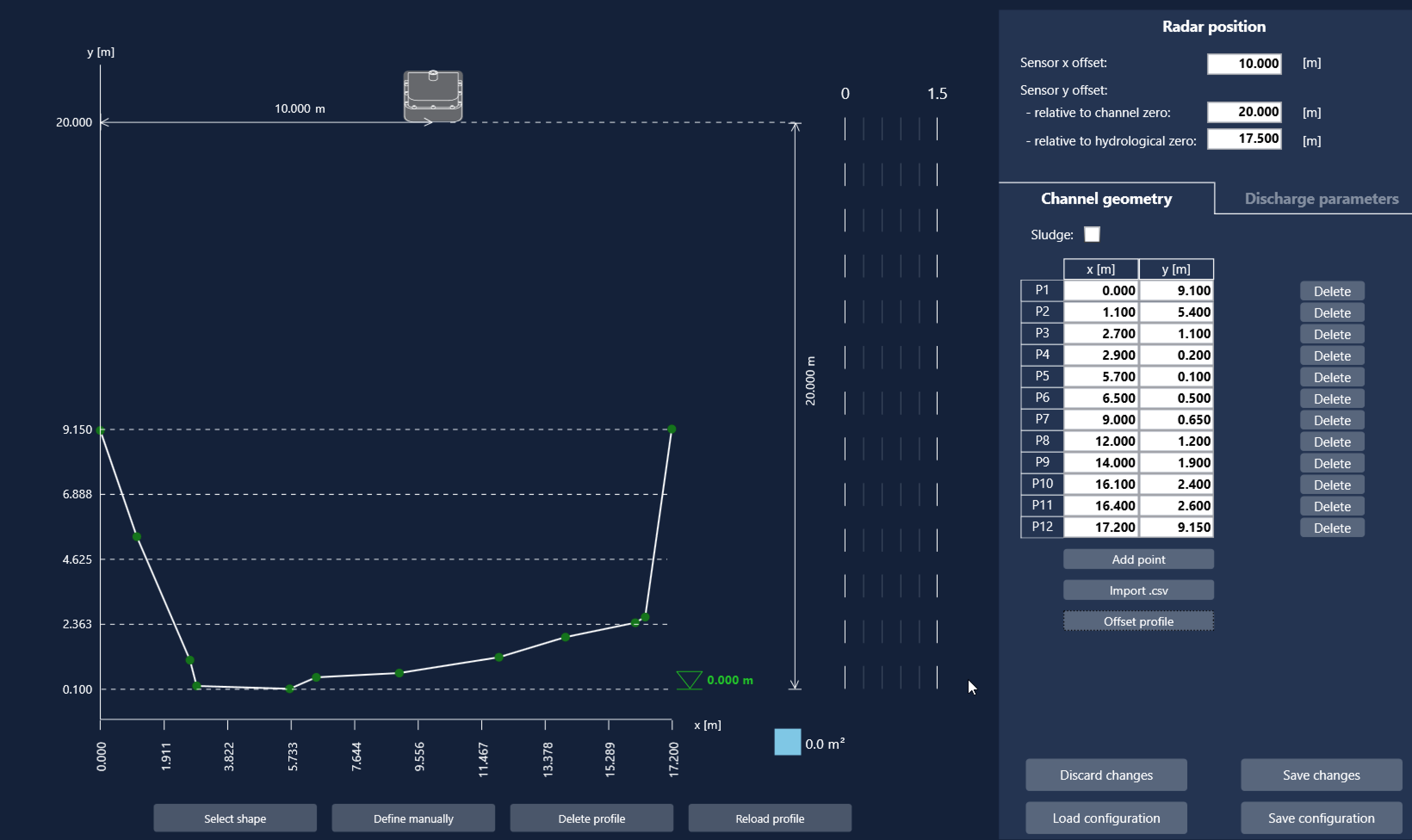
Channel profile with radar position.#
Defining Discharge Parameters#
The final step is to define the k-factor table.
Open Discharge parameters and add k-factor values for the required water levels using Add k-factor. Alternatively, click Estimate k-factors to generate an initial estimate.
If no k-factor is defined, a default value of 1.0 is used.
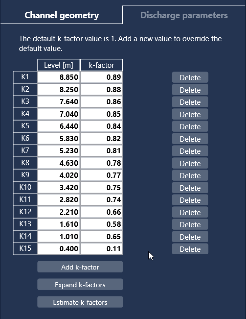
K-factor editor.#
The configured k-factors are displayed next to the channel profile and aligned with their corresponding water levels.
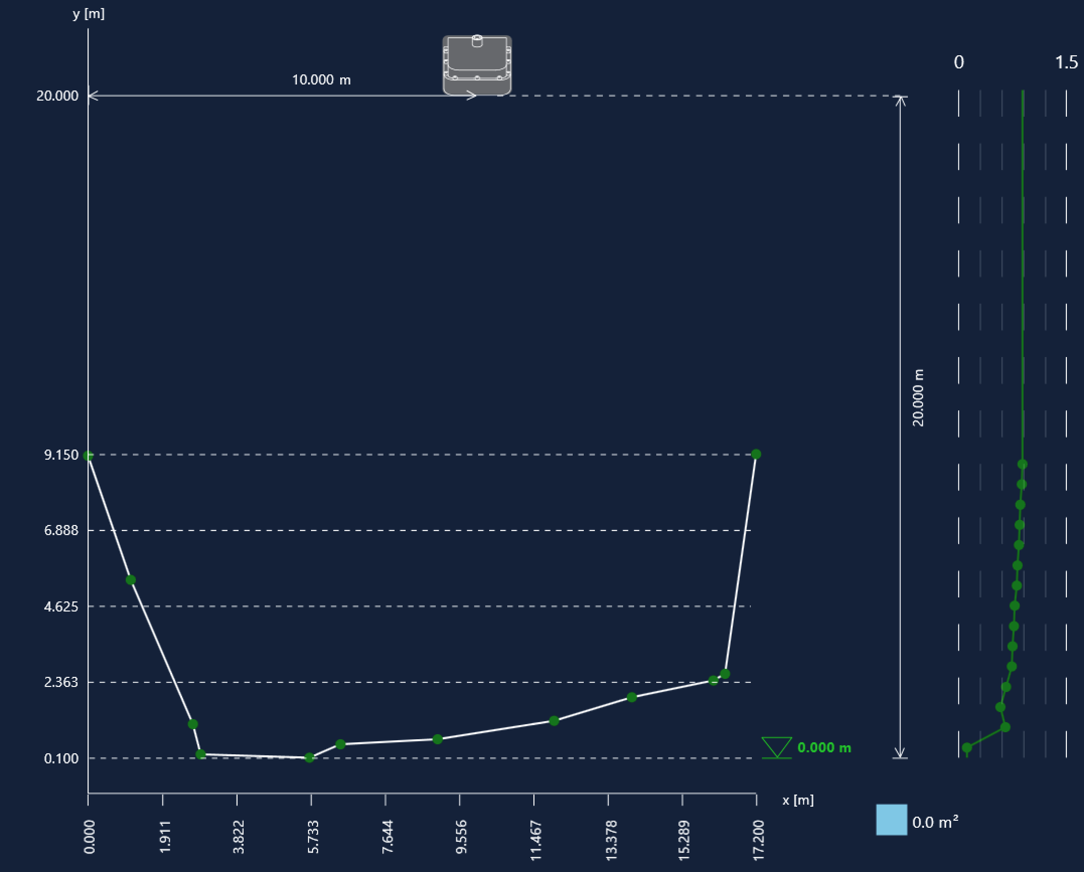
Channel profile with configured k-factors.#
After configuring the profile and discharge parameters, click Save changes to store the configuration on the device.
To discard all unsaved modifications and restore the current device configuration, click Discard changes.
The configuration can also be saved to an XML file using Save configuration. To restore a previously saved configuration, click Load configuration, then save it to the device using Save changes.
To remove the current channel profile, click Delete profile. To immediately create a new profile, click Define manually or Select profile shape.
Defining Channel Profile from a Predefined Shape#
Click Select profile shape to choose one of the available predefined channel geometries.
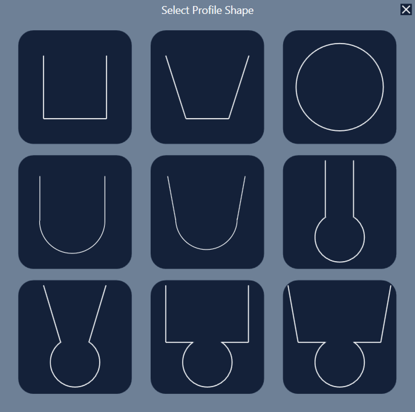
Selecting a predefined channel shape.#
After selecting a shape, enter the required dimensions and select the measurement unit. The entered dimensions are illustrated in the preview.
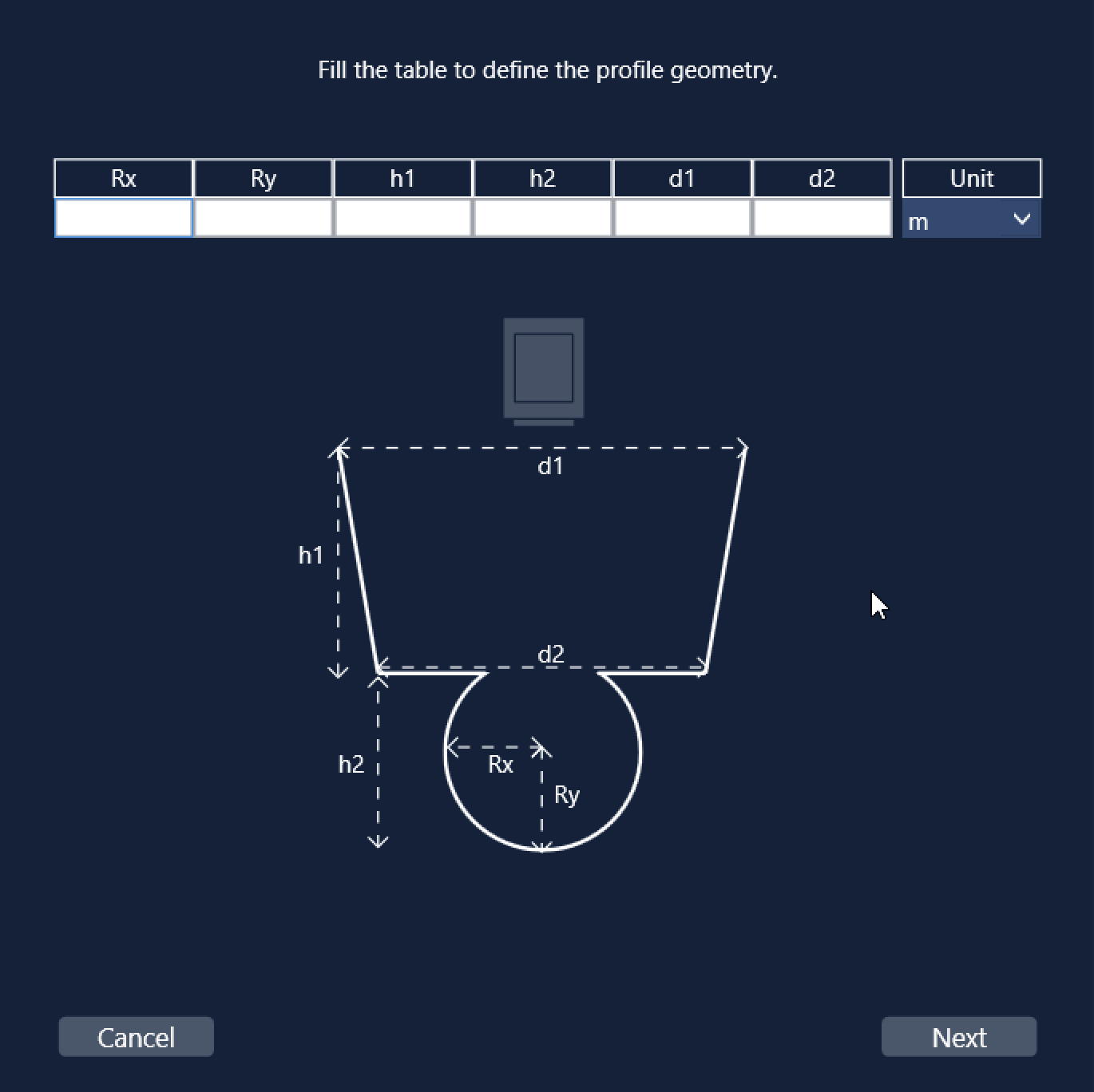
Entering channel dimensions.#
Click Next to configure the radar height. The required measurement is illustrated together with the previously entered dimensions.
If necessary, click Back to modify the channel dimensions.
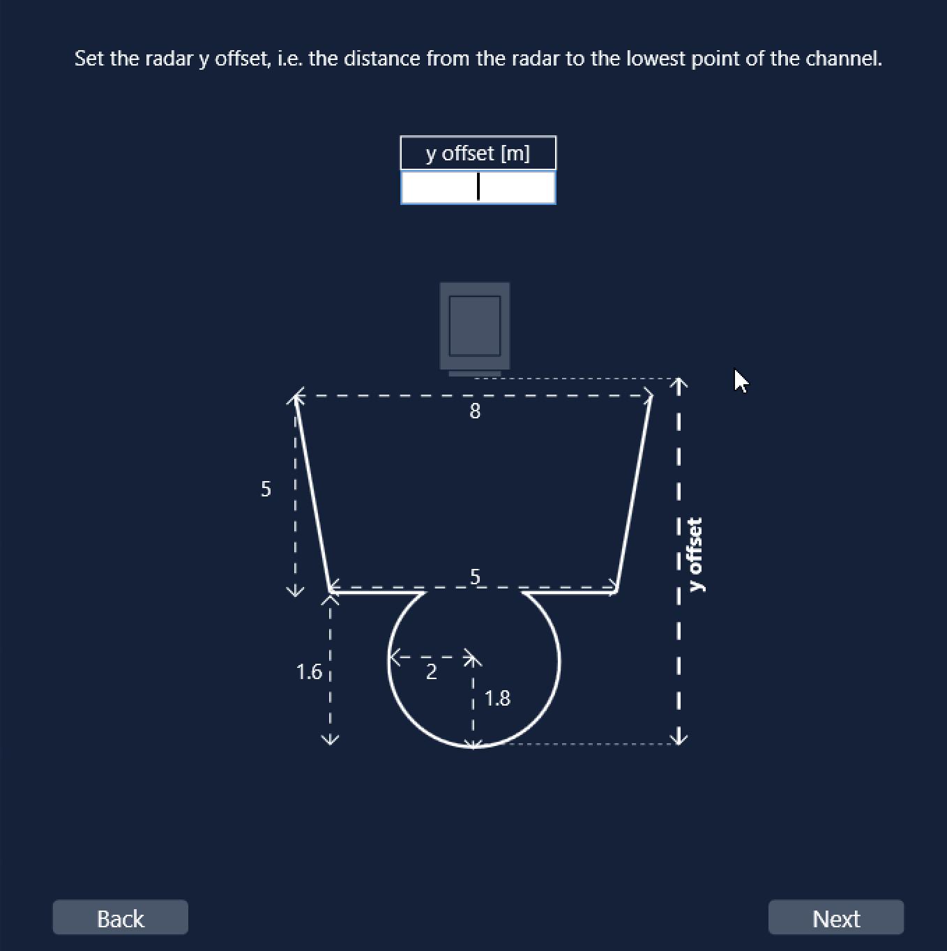
Configuring radar position.#
After the radar position has been configured, the channel profile is displayed in the main window.
The remaining step is to configure the k-factors in the Discharge parameters section, either manually or by using Estimate k-factors, as described earlier.
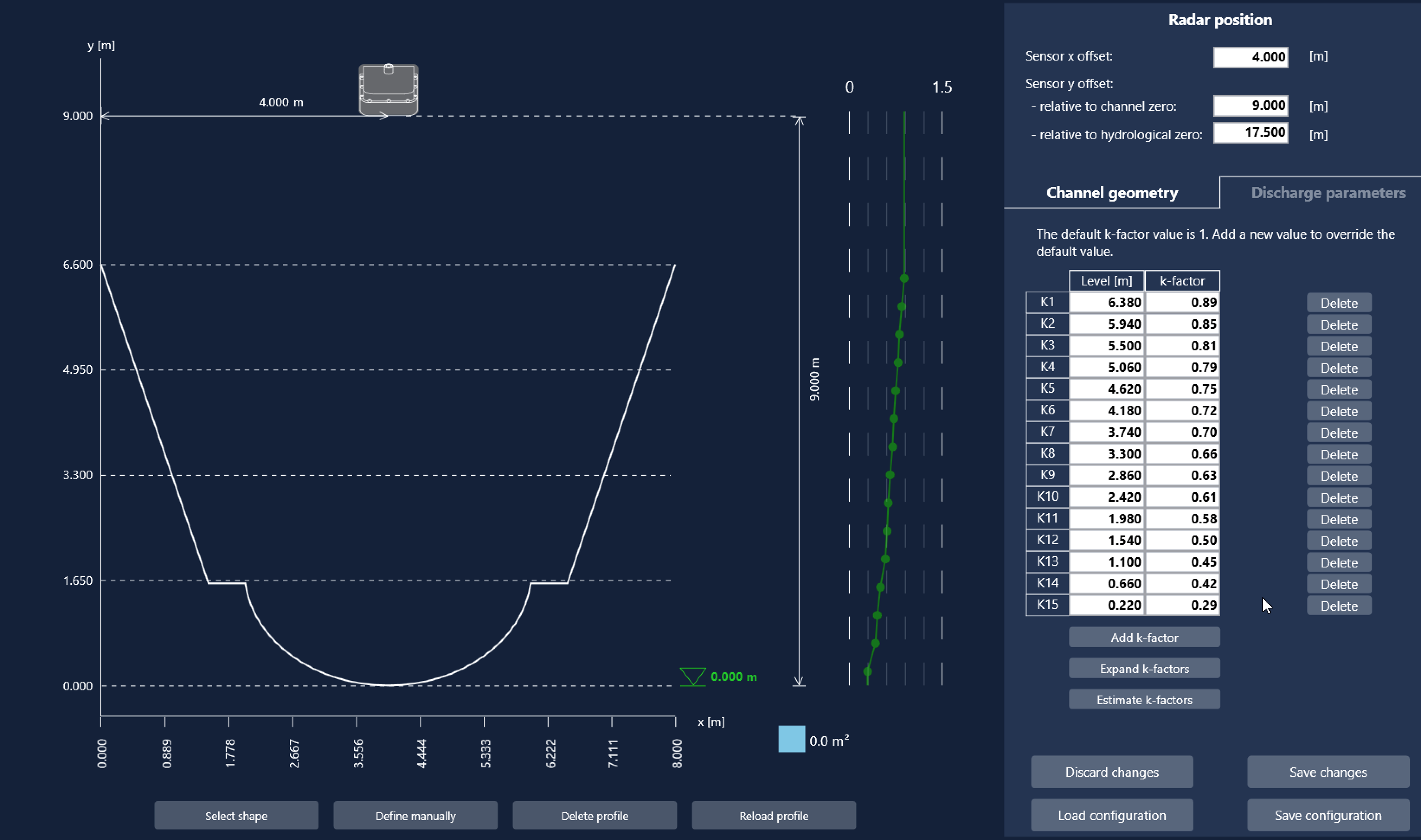
Completed discharge configuration using a predefined channel shape.#
Defining Sludge Depth#
In sewer systems and other sediment-prone channels, sludge accumulation reduces the effective flow area. Configure the sludge depth so the FX200 can correctly calculate the wetted cross-section.
Enable Sludge in the Channel geometry pane and enter the sludge thickness. The accumulated sludge is immediately displayed in the channel profile.
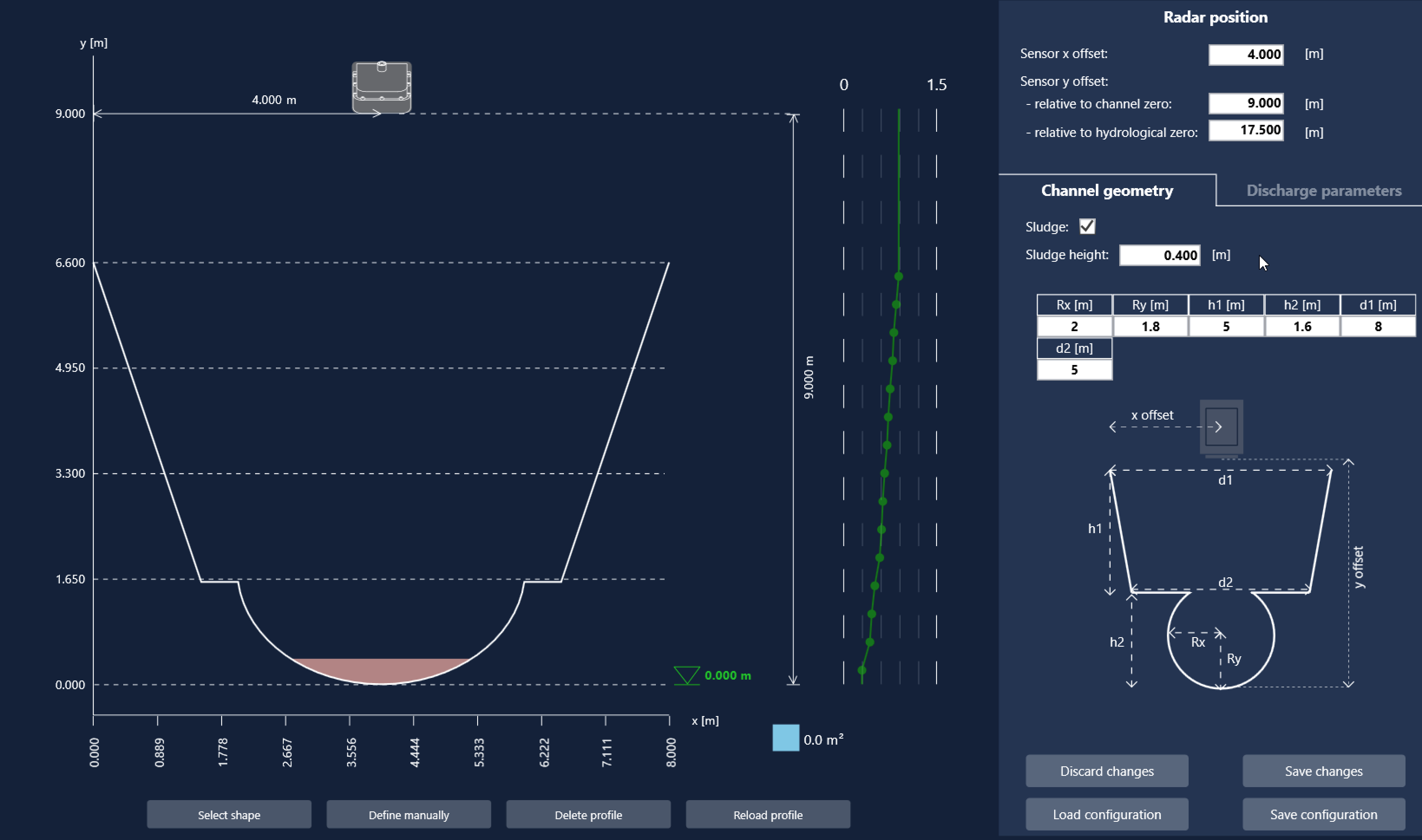
Channel profile with sludge compensation.#