4. Flow Meter Settings#
This chapter groups the configurable device parameters exposed through the configurator and device protocols.
RS-232 Baud Rate#
Configures the baud rate (bits per second) for serial communication on the RS-232 data line. This setting controls how many bits are sent on the communication line in one second. The available values are standardized. Using higher baud rate over longer lines may introduce errors in transferred data. The default instrument baud rate is 115200 bps.
RS-485 Baud Rate#
Configures the baud rate (bits per second) for serial communication on the RS-485 data line. This setting controls how many bits are sent on the communication line in one second. The available values are standardized. Using higher baud rate over longer lines may introduce errors in transferred data. The default instrument baud rate is 9600 bps.
Modbus ID#
Configures the device (slave) ID to be used on Modbus interface protocol. Modbus protocol uses request/response format and allow multiple instruments to be connected on the same bus. When a remote master transmits the request message, it will use the device ID as a device address. All instruments will receive the request, but only the instrument with matching device ID will answer to the received request.
Modbus Parity#
Parity is used in serial communication as a basic method of bit-level error detection. When parity is set to None, no parity bit is added to the transmitted data. In this case, no bit-level error checking is performed. When Even or Odd parity is selected, an additional parity bit is appended to each transmitted byte. This bit is set so that the total number of logical “1” bits in the byte (including the parity bit) is either even or odd, depending on the selected mode. If the receiving device detects that the calculated parity does not match the received parity bit, a communication error is identified.
For most Modbus devices, the default and commonly used setting is Even parity.
RS-485 Stop Bits#
Stop bits are added to the end of each data byte transferred over serial line, to allow pause between the two bytes of data. One or two stop bits may be used. The default setting for most Modbus devices is one stop bit, but some dataloggers require that two stop bits be used.
SDI-12 ID#
Configures the SDI-12 device ID to be used on SDI-12 interface. SDI-12 protocol uses request/response format and allows multiple instruments to be connected on the same bus. When a remote master transmits the request message, it will use the device ID as a device address. All instruments will receive the request, but only the instrument with matching device ID will answer to the received request.
4 - 20 mA Output Type#
Selects which measurement parameter is transmitted via the analog 4–20 mA output. The user can choose between discharge (flow), water level, distance to the water surface, surface velocity, or total volume.
4 - 20 mA Minimum Value#
To configure the 4-20 mA output range, the minimum measured value corresponding to 4 mA must be defined. The value is entered and the corresponding measurement unit (e.g., m³/s, cfs, L/h) is selected. This setting determines the lower point of the linear scaling between the measured velocity and the analog output current.
Example:
If the expected measurement range is between 0.700 m³/s and 1.500 m³/s, it is recommended to set the 4 mA value slightly below the lowest expected measurement (e.g., 0.500 m³/s). This ensures proper scaling and avoids signal saturation at the lower end of the operating range.
If measurement resolution is not critical, the minimum value for the 4-20 mA output may alternatively be left at the instrument minimum of 0 m³/s.
4 - 20 mA Maximum Value#
To configure the 4-20 mA output range, the maximum measured value corresponding to 20 mA must be defined. The value is entered and the corresponding measurement unit (e.g., m³/s, cfs, L/h) is selected. This setting determines the higher point of the linear scaling between the measured velocity and the analog output current.
Example:
If the expected measurement range is between 0.700 m³/s and 1.500 m³/s, it is recommended to set the 20 mA value slightly above the highest expected measurement (e.g., 1.700 m³/s). This ensures proper scaling and avoids signal saturation at the higher end of the operating range.
If measurement resolution is not critical, the maximum value for the 4-20 mA output may alternatively be left at the instrument maximum of 16.000 m³/s.
Filter Length#
This parameter defines the length of the averaging filter, in seconds, used to smooth the measured velocity and water level values.
A longer filter length means that a greater number of individual measurements are included in the averaging process, resulting in smoother and more stable output data. However, increasing the filter length also increases the response time of the instrument. When surface velocity or water level changes, a longer filter will cause a slower transition to new reported values.
In most applications, the recommended setting is between 10 and 30 seconds. For highly turbulent flow conditions, a longer filter length is recommended to achieve more stable measurement results.
Direction Filter#
The Direction Filter parameter determines whether the instrument measures flow in both directions or restricts detection to a single flow direction (incoming or outgoing).
When set to No Filter, the radar measures velocity regardless of flow direction and reports both the velocity magnitude and the detected flow direction.
When set to Incoming or Outgoing, the instrument processes and reports only the selected flow direction. Radar returns corresponding to the opposite direction are ignored.
At monitoring sites where flow is expected to occur consistently in only one direction, it is strongly recommended to configure the Direction Filter accordingly. Restricting the measurement to the expected flow direction improves measurement stability and consistency by eliminating unwanted signal components.
SNR Threshold#
Defines the minimum signal-to-noise ratio (SNR), in dB, required for the radar to report a velocity measurement. Values below this threshold are ignored and zero velocity is reported.
A low SNR indicates that the radar signal is weak compared to the background noise , which can result in uncertain or incorrect velocity readings. Increasing this threshold helps filter out unreliable measurements. If you notice the radar reporting velocities when the water is not moving, check the SNR values during those periods. If they are consistently lower than during valid measurements, consider increasing the SNR threshold.
This parameter affects only surface velocity measurement, and not water level measurement.
Beam Width#
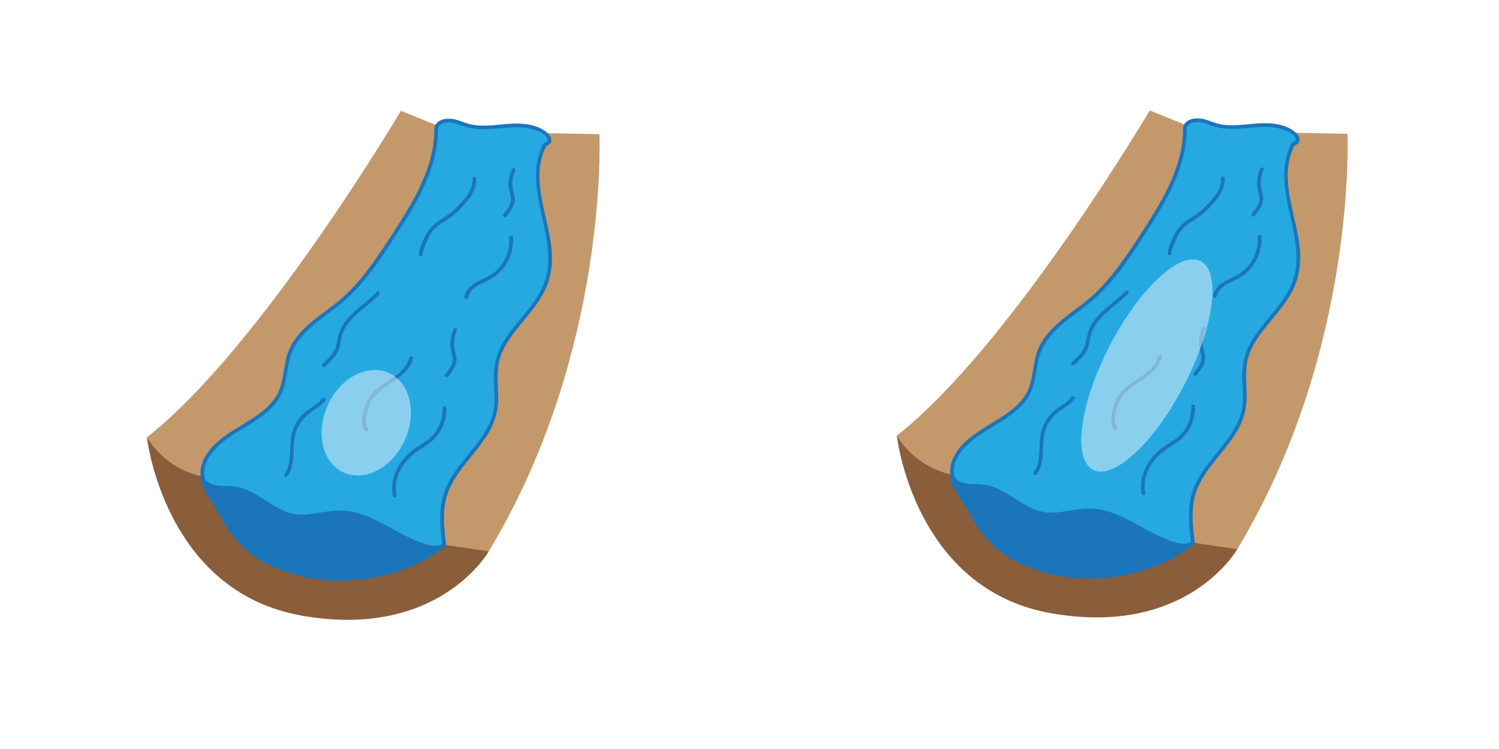
Narrow / wide radar beam width selection.#
Beam Width defines the elevation spread of the radar beam and therefore how long a section of the water surface is analyzed. A narrower beam focuses on a shorter area close to the sensor, making it ideal when you want to exclude local disturbances such as waterfalls, cascades, or strong turbulence near the installation. A wider beam covers a longer surface area, allowing the radar to observe and average velocities over a broader section of the river or stream.
Because the radar reports an average velocity within the observed area, a wider beam is useful when surface velocities vary gradually, while a narrower beam provides more stable results in the presence of local disturbances.
The beam width of the water level radar is not affected by this parameter.
Beam Position#
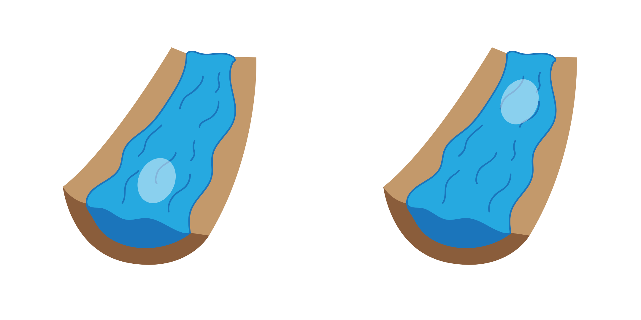
Near / far radar beam position selection.#
The Beam Position parameter defines the measurement zone on the water surface (either near or far), placed along the radar beam, where the surface velocity is analyzed.
The default setting is Near, which configures the radar to measure velocities closer to the instrument. This setting is suitable for most standard installations.
In certain situations, the water surface closer to the radar may be more turbulent or disturbed than areas farther away. In such cases, setting the Beam Position to Far shifts the measurement zone further from the instrument, which may result in more stable and representative velocity readings.
The beam position of the water level radar is not affected by this parameter.
Discharge Output Unit#
This parameter defines the measurement unit in which the radar’s discharge readings are transmitted over all communication interfaces, including RS-232 (NMEA-like protocol), RS-485 (Modbus), and SDI-12.
Select the unit that matches the requirements of your data logger, SCADA system, or telemetry platform to ensure proper scaling, interpretation, and integration of the measurement data.
Water Level Output Unit#
This parameter defines the measurement unit in which the radar’s water level readings are transmitted over all communication interfaces, including RS-232 (NMEA-like protocol), RS-485 (Modbus), and SDI-12.
Select the unit that matches the requirements of your data logger, SCADA system, or telemetry platform to ensure proper scaling, interpretation, and integration of the measurement data.
Surface Velocity Output Unit#
This parameter defines the measurement unit in which the radar’s surface velocity readings are transmitted over all communication interfaces, including RS-232 (NMEA-like protocol), RS-485 (Modbus), and SDI-12.
Select the unit that matches the requirements of your data logger, SCADA system, or telemetry platform to ensure proper scaling, interpretation, and integration of the measurement data.
Volume Output Unit#
This parameter defines the measurement unit in which the radar’s calculated totalized flow volume is transmitted over all communication interfaces, including RS-232 (NMEA-like protocol), RS-485 (Modbus), and SDI-12.
Select the unit that matches the requirements of your data logger, SCADA system, or telemetry platform to ensure proper scaling, interpretation, and integration of the measurement data.
Maximum Velocity#
The Maximum Velocity setting defines the maximum expected surface flow velocity at the measurement site. The instrument will not report any velocity value higher than the configured maximum. Any detected value above this limit will be automatically rejected. This setting is useful for eliminating occasional spurious readings that may occur due to strong turbulence, debris passing through the radar beam, temporary signal disturbances, and environmental effects such as splashes or floating objects.
By setting a realistic maximum velocity based on site conditions, the reliability of the reported data can be improved.
Important: The configured value should be slightly higher than the highest velocity expected at the site. If the value is set too low, valid high-flow measurements may be incorrectly discarded.
Minimum Distance#
Defines the minimum valid distance between the radar and the water surface. Reflections detected closer than this value are ignored. This helps to eliminate unwanted signals from nearby objects such as bridge structures or mounting elements.
Important: Set this value slightly below the shortest expected distance to the water surface.
Maximum Distance#
Defines the maximum valid distance between the radar and the water surface. Reflections detected beyond this value are ignored. This prevents the instrument from processing signals outside the actual water surface area.
Important: Set this value slightly above the longest expected distance to the water surface, considering water level variations.
Dynamic Flow Profiler#
The Dynamic Flow Profiler (DFP) is an AI-based algorithm that improves measurement reliability under challenging conditions. When enabled, the instrument analyzes historical velocity data and learns the relationship between surface velocity and water level at the site. If the radar is temporarily unable to measure velocity due to low signal-to-noise ratio (SNR), smooth water surface, or other disturbances, DFP will estimate the velocity instead of reporting zero. The estimated value is calculated using previously recorded measurements and their correlation with the current water level. This function is especially useful at sites with very smooth water surfaces and weak radar reflections.
Important:
The instrument requires a training period to learn site-specific flow behavior. During this time, performance gradually improves.
If the radar is repositioned or installed at a new site, the DFP model must be reset. Click the Reset DFP button to clear previously learned data.
Power Management#
Switching the device between continuous scanning mode and SDI-12 automatic sleep mode.
In continuous scanning mode, the device constantly performs measurements, which are transmitted over RS-232 interface and made available over Modbus, SDI-12, and analog interfaces. RS-232 measurement sentences are transmitted when NMEA output is enabled. When awake, the device is available over RS-232 and Modbus interfaces, and is responding to commands on these interfaces.
In SDI-12 automatic sleep mode, the device remains in low-power sleep mode until SDI-12 measure command is received (aM!). While in sleep mode, the device will not be able to connect to Modbus or RS-232 interface. For the reconfiguration of the device which is set to operate in SDI-12 automatic sleep mode, it is necessary to power-cycle the device then use the PC configurator application to connect to the device within 1 minute after power-up. If there is no attempt to connect to the device over RS-232 within one minute, the device will automatically go back to the sleep mode. Additionally, it is possible to send the custom SDI-12 command aXGLWU! That will also wake up the device from the sleep mode, and keep it running for 1 minute to allow the PC application enough time to establish the connection to the device.
Operation Mode#
Allows switching the device from operating mode to standby mode and back. While the device is in standby mode, it will communicate through communication interfaces, but no measurements will be made. In operating mode, the device continuously performs measurements. In standby mode, the power consumption is reduced.
Enable WiFi#
Enables on-baord WiFi access point which allows wireless connection to the device for re-configuration and data access. With WiFi access enabled, the device power consumption will be approx. 40 mA higher (at 12V).
WiFi Password#
Set the WiFi access point password. When the device start connecting to the on-board WiFi access point, the instrument will ask for the conencting device to enter this password. The password must be at least 8 characters long.
LiDAR Mode#
Enables or disables automatic scanning of the channel cross-section with the built-in LiDAR sensor. The available values are:
off= automatic scanning is disabled,automatic= the instrument scans the channel cross-section periodically.
When automatic mode is enabled, the instrument performs a scan on every power-up and then repeats the scan at the interval defined by the LiDAR scan period. Each completed automatic scan replaces the stored channel profile, so the discharge calculation always uses the most recent cross-section. This is useful at sites where the channel bed changes over time, for example due to sediment transport or scouring.
When automatic mode is disabled, the channel profile changes only when a manual scan is performed and saved, or when the profile is edited manually.
Regardless of the selected mode, a scan can always be started manually, as described in Manual LiDAR Scan.
LiDAR Scan Period#
Defines the interval, in minutes, between two consecutive automatic LiDAR scans. The valid range is between 1 and 32767 minutes, and the default value is 15 minutes.
This setting is used only when the LiDAR mode is set to automatic. Since each scan requires the LiDAR and its motor to run, more frequent scanning increases the average power consumption of the instrument. At sites with a stable channel bed, a long scan period is sufficient.
Left Limit Angle#
Defines how far the LiDAR sweep extends towards the left side of the channel, in degrees measured from the vertical axis of the instrument. The default value of 70° corresponds to the full mechanical sweep range of the sensor, and values above 70° have no additional effect.
Reduce this value to exclude a part of the scanned sector from the measured channel profile, for example when a bridge structure, a bank wall, or vegetation on the left side of the channel is scanned instead of the channel bed.
Right Limit Angle#
Defines how far the LiDAR sweep extends towards the right side of the channel, in degrees measured from the vertical axis of the instrument. The default value of 70° corresponds to the full mechanical sweep range of the sensor, and values above 70° have no additional effect.
Reduce this value to exclude a part of the scanned sector from the measured channel profile, for example when a bridge structure, a bank wall, or vegetation on the right side of the channel is scanned instead of the channel bed.
Manual LiDAR Scan#
A single LiDAR scan can be started at any time, independently of the configured LiDAR mode. A manual scan takes 30 to 45 seconds to complete, and its result is not applied to the discharge calculation until it is reviewed and saved. The procedure is described in 6.3. Using LiDAR.
A manual scan can also be started remotely, over the servicing protocol (Start Manual LiDAR Scan), over Modbus (Block 3: Configuration Registers (R/W)), or over SDI-12 (Start Manual LiDAR Scan).
While a scan is in progress, no new scan can be started. Whether a scan is currently running, and whether it is an automatic or a manual one, is reported by the servicing protocol as described in Check LiDAR Scan Status.