3.1. Instrument Mounting and Radar Beam Size#
Instrument Mounting#
Proper site selection and correct installation are essential to achieve the specified measurement accuracy.
The instrument should be aligned parallel to the direction of water flow. Any deviation from the flow direction will reduce the measured velocity value. The measured value will always be lower than the actual surface velocity if the instrument is not properly aligned. It is recommended to point the instrument upstream, so the water flows toward the sensor.
Radar Beam Width#
The installation height and tilt angle determine the size and position of the radar measurement areas on the water surface. The FX200 uses two separate radar beams: one for surface velocity measurement and one for water level measurement. The surface velocity radar illuminates an elliptical measurement area on the water surface. The instrument reports the average surface velocity within this area. The water level radar is directed vertically downward and forms a circular measurement area directly beneath the sensor.
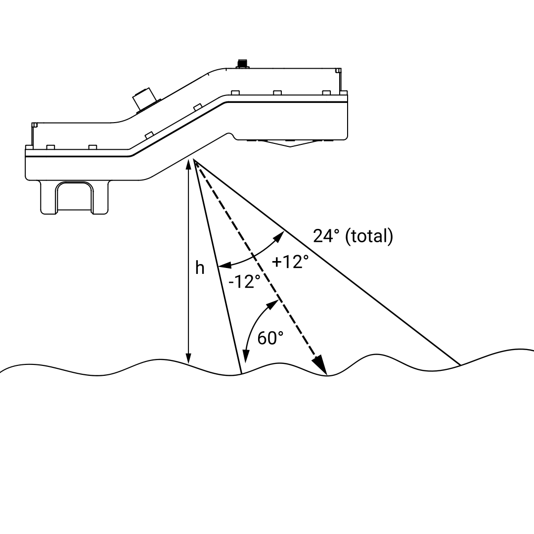
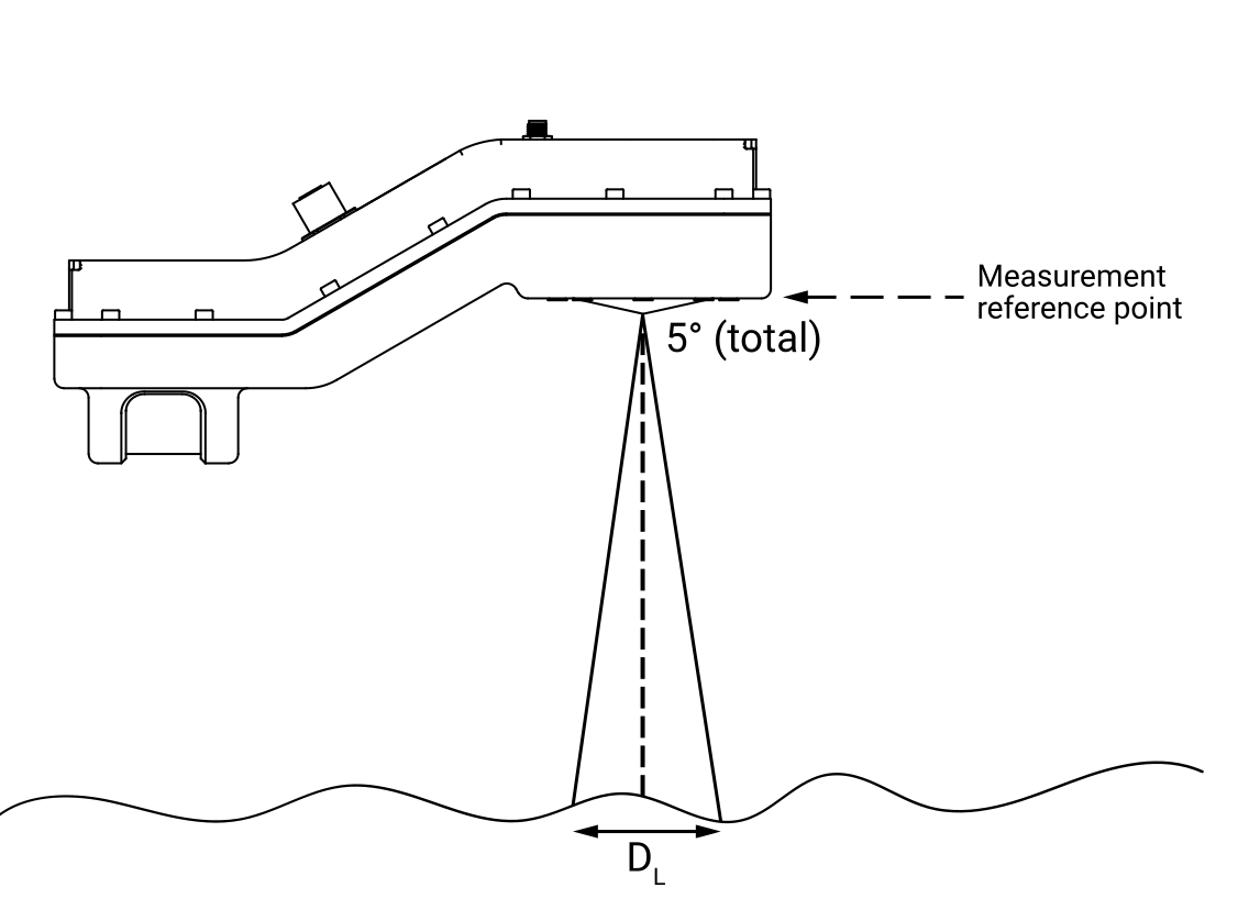
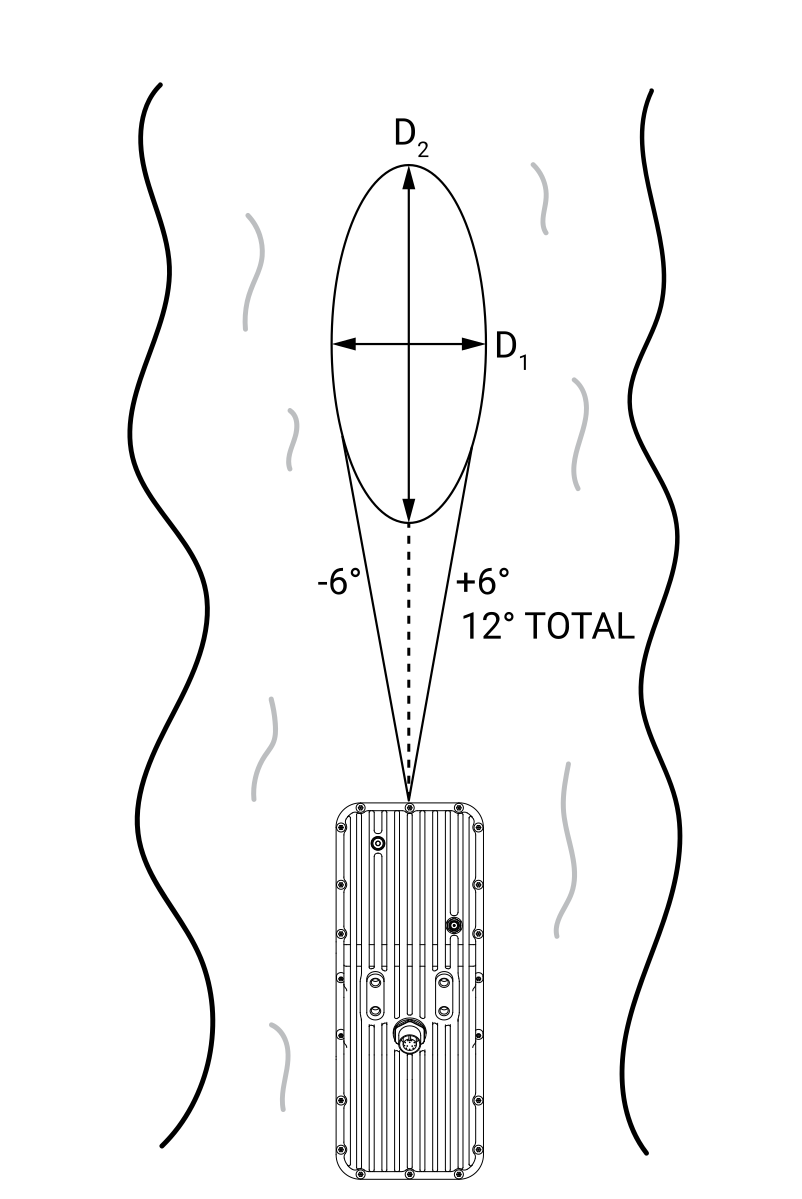
The dimensions of both the ellipse and the circle depend on the installation height of the instrument above the water surface. The formulas used to calculate the diameters of these measurement areas, along with a table showing the diameters for various installation heights, are provided below.
Height (m) |
D1 (m) |
D2 (m) |
Dl (3) |
|---|---|---|---|
1 |
0.24 |
0.58 |
0.09 |
2 |
0.48 |
1.15 |
0.17 |
5 |
1.21 |
2.88 |
0.44 |
10 |
2.43 |
5.75 |
0.87 |
20 |
4.85 |
11.51 |
1.75 |
30 |
7.28 |
17.26 |
2.62 |
Height (ft) |
D1 (ft) |
D2 (ft) |
Dl (ft) |
|---|---|---|---|
5 |
1.21 |
2.88 |
0.44 |
10 |
2.43 |
5.75 |
0.87 |
20 |
4.85 |
11.51 |
1.75 |
30 |
7.28 |
17.26 |
2.62 |
60 |
14.56 |
34.53 |
5.24 |
90 |
21.84 |
51.80 |
7.86 |
Controlling Radar Beam#
Unlike traditional Doppler-based radars, the surface velocity sensor of the FX200 uses frequency-modulated technology that enables advanced control of the effective measurement area on the water surface.
The previous section describes the maximum radar beam footprint, which is defined by the antenna geometry and installation conditions. However, the FX200 does not need to use the entire footprint. Through modulation control and signal processing, the instrument can limit measurements of the surface velocity to a selected portion of that area. This allows the user to focus on the most representative flow conditions and avoid disturbed or non-uniform regions.
Beam Control Parameters#
The FX200 provides two configurable parameters for adjusting the measurement area:
1. Beam Width
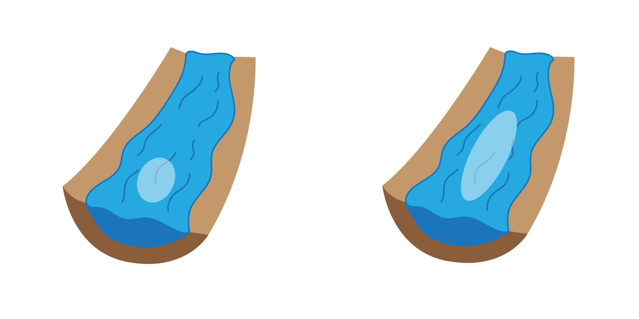
This parameter controls the size of the measurement area in the elevation direction (i.e., effectively reduces the D2 diameter of the ellipse).
Available options:
Narrow – restricts measurements to a smaller, more focused region; recommended when flow disturbances are present and a more stable region must be isolated
Wide – uses a larger portion of the radar beam; suitable for uniform flow conditions
2. Beam Offset
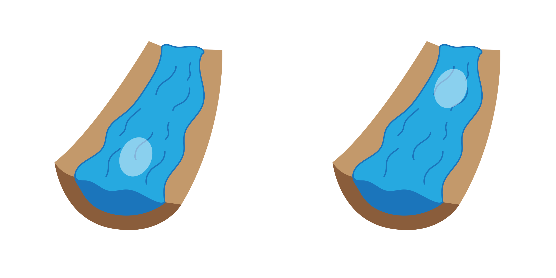
This parameter defines the position of the measurement area within the overall radar footprint. It allows the user to shift the active measurement zone along the flow direction.
Available options:
Near – measurement area is closer to the sensor
Far – measurement area is further away from the sensor
Radar Beam Configuration Matrix#
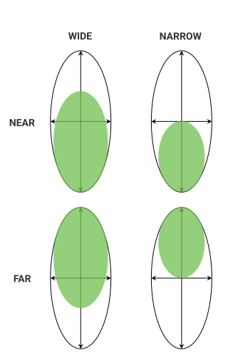
Effect of beam parameters on active scanning area.#
Correctly Adjusting Beam Width and Position#
In real-world installations, flow conditions are often non-uniform. Turbulence, obstacles, or channel geometry can create areas where velocity measurements are not representative of the average surface flow. By combining Beam Width and Beam Offset, the VX60 allows the user to target the most stable portion of the flow.
Example 1 – Upstream cascade or turbulence away from the sensorDisturbance located further from the mounting point.Recommended settings:- Beam Width: Narrow- Beam Offset: Near
—
Example 2 – Turbulence near a bridge pier or mounting structureDisturbance located close to the sensor.Recommended settings:- Beam Width: Narrow- Beam Offset: Far
—
Example 3 – No disturbace or turbulenceThe water flow is uniform.Recommended settings:- Beam Width: Wide- Beam Offset: Near