6. AX500 Air Quality Meter Settings#
This chapter groups the configurable device parameters exposed through the configurator and device protocols.
Baud Rate#
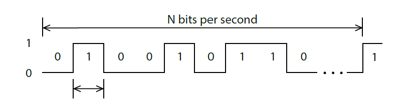
RS-232 Baud Rate#
Configures the baud rate (bits per second) for serial communication on the RS-232 data line. This setting controls how many bits are sent on the communication line in one second. The available values are standardized. Using higher baud rate over longer lines may introduce errors in transferred data. The default instrument baud rate is 115200 bps.
RS-485 Baud Rate#
Configures the baud rate (bits per second) for serial communication on the RS-485 data line. This setting controls how many bits are sent on the communication line in one second. The available values are standardized. Using higher baud rate over longer lines may introduce errors in transferred data.
Device ID#
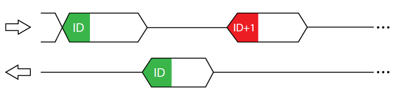
Modbus ID#
Configures the device (slave) ID to be used on Modbus interface protocol. Modbus protocol uses request/response format and allow multiple instruments to be connected on the same bus. When a remote master transmits the request message, it will use the device ID as a device address. All instruments will receive the request, but only the instrument with matching device ID will answer to the received request.
SDI-12 ID#
Configures the SDI-12 device ID to be used on SDI-12 interface. SDI-12 protocol uses request/response format and allows multiple instruments to be connected on the same bus. When a remote master transmits the request message, it will use the device ID as a device address. All instruments will receive the request, but only the instrument with matching device ID will answer to the received request.
Parity#
Modbus Parity#
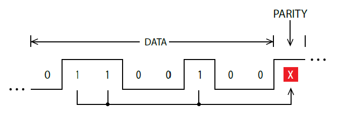
Parity is used in serial communication as a basic method of bit-level error detection. When parity is set to None, no parity bit is added to the transmitted data. In this case, no bit-level error checking is performed. When Even or Odd parity is selected, an additional parity bit is appended to each transmitted byte. This bit is set so that the total number of logical “1” bits in the byte (including the parity bit) is either even or odd, depending on the selected mode. If the receiving device detects that the calculated parity does not match the received parity bit, a communication error is identified.
Serial Parity#
Parity is used in serial communication as a basic method of bit-level error detection. When parity is set to None, no parity bit is added to the transmitted data. In this case, no bit-level error checking is performed. When Even or Odd parity is selected, an additional parity bit is appended to each transmitted byte. This bit is set so that the total number of logical “1” bits in the byte (including the parity bit) is either even or odd, depending on the selected mode. If the receiving device detects that the calculated parity does not match the received parity bit, a communication error is identified.
Stop Bits#
RS485 Stop Bits#
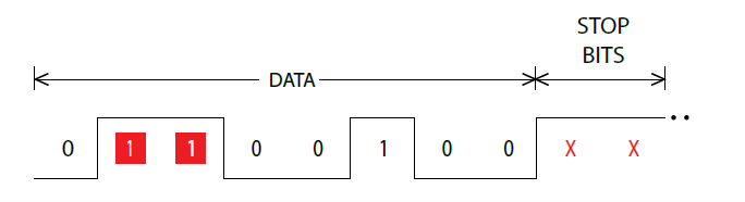
Stop bits are added to the end of each data byte transferred over serial line, to allow pause between the two bytes of data. One or two stop bits may be used. The default setting for most Modbus devices is one stop bit, but some dataloggers require that two stop bits be used.
RS232 Stop Bits#
Stop bits are added to the end of each data byte transferred over serial line, to allow pause between the two bytes of data. One or two stop bits may be used.
Blowout period#
The blowout period defines the interval between automatic blowout cycles, expressed in minutes. During a blowout cycle, the device briefly activates an air pump to remove accumulated dust and particles from the sensors and measurement chamber. Setting the blowout period to 0 disables automatic blowout cycles. In this case, blowout can only be started manually.
Power Management#
The device supports two operating modes: continuous scanning mode and SDI-12 sleep mode.
In continuous scanning mode, the device continuously performs measurements. Measurement data is transmitted over the RS-232 interface and is also available through the Modbus and SDI-12 interfaces. In this mode, the device remains continuously available over the RS-232 and Modbus interfaces.
In SDI-12 sleep mode, the device remains in a low-power sleep state until an SDI-12 Measure command, such as aM!, is received. While the device is in sleep mode, communication over the Modbus and RS-232 interfaces is not available.