5. Connecting sensor#
The AX500 uses robust IP68 circular M12 connector with 12 positions and a mating cable, both delivered as a standard feature with the instrument. The connector and cable details are shown in Figure 3 while Table 3 gives a detailed description of each pin.
Connector Drawing#
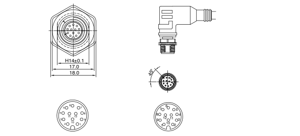
Figure 3. Device Connector#
Both the chassis connector (left) and cable connector (right) are shown from the front.
Connector Pin-Out#
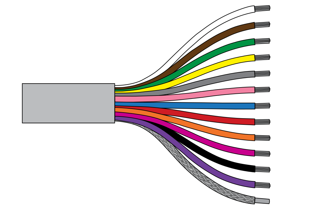
Figure 4. Wire colouring#
The table below describes the function of each pin.
Table 3. Connector and Cable Pin-out
Pin No. |
Wire Color |
Pin Name |
Pin Description |
|---|---|---|---|
1 |
White |
Power Ground |
Connect to the negative (–) terminal of the power supply. |
2 |
Brown |
Power Input |
Power supply input. The supply voltage must be between 9–27 VDC. The power source must be capable of providing at least 500 mA |
3 |
Green |
RS232 TX |
RS-232 transmit data signal (device → host). |
4 |
Yellow |
RS232 RX |
RS-232 receive data signal (host → device). |
5 |
Grey |
Signal Ground |
Signal ground reference for RS-232 or SDI-12 communication. |
6 |
Pink |
Not Used |
Not Used |
7 |
Blue |
Not Used |
Not Used |
8 |
Bright Red |
Not Used |
Not Used |
9 |
Orange |
RS485 B- |
RS-485 data low (inverting) signal. |
10 |
Dark Red |
RS485 A+ |
RS-485 data high (non-inverting) signal. |
11 |
Black |
SDI-12 Data |
SDI-12 communication data line. |
12 |
Purple |
4-20 mA Loop- |
Negative terminal of the active 4–20 mA output. |
13 |
Clear |
Shield |
Cable shield. Connect to grounding. |